I denna laboration ska du träna dig på att redigera en befintlig access control list (ACL) med syfte att modifiera reglerna i en ACL. Du kommer att lägga till, ta bort eller ändra enskilda regler (ACE) utan att behöva ta bort hela listan. Detta är en viktig färdighet för att kunna anpassa nätverkspolicys vid förändrade behov.
| Device | Interface | IP Address | Subnet Mask | Default Gateway |
|---|---|---|---|---|
| R1 | G0/0/0 | 192.168.10.1 | 255.255.255.0 | N/A |
| G0/0/1 | 192.168.20.1 | 255.255.255.0 | ||
| S0/1/0 (DCE) | 10.1.1.1 | 255.255.255.252 | ||
| Edge | S0/1/0 | 10.1.1.2 | 255.255.255.252 | N/A |
| S0/1/1 (DCE) | 10.2.2.2 | 255.255.255.252 | ||
| S0/2/1 | 209.165.200.225 | 255.255.255.224 | ||
| R3 | G0/0/0 | 192.168.30.1 | 255.255.255.0 | N/A |
| G0/0/1 | 192.168.40.1 | 255.255.255.0 | ||
| S0/1/1 | 10.2.2.1 | 255.255.255.252 | ||
| S1 | VLAN 1 | 192.168.10.11 | 255.255.255.0 | 192.168.10.1 |
| S2 | VLAN 1 | 192.168.20.11 | 255.255.255.0 | 192.168.20.1 |
| S3 | VLAN 1 | 192.168.30.11 | 255.255.255.0 | 192.168.30.1 |
| S4 | VLAN 1 | 192.168.40.11 | 255.255.255.0 | 192.168.40.1 |
| PC-A | NIC | 192.168.10.3 | 255.255.255.0 | 192.168.10.1 |
| PC-B | NIC | 192.168.20.3 | 255.255.255.0 | 192.168.20.1 |
| PC-C | NIC | 192.168.30.3 | 255.255.255.0 | 192.168.30.1 |
| PC-D | NIC | 192.168.40.3 | 255.255.255.0 | 192.168.40.1 |
Observera: Denna laboration behålls på engelska för att stämma överens med Ciscos officiella terminologi, kommandon och dokumentation.
Objectives
- Part 1: Verify Connectivity
- Part 2: Configure and Verify Standard Numbered and Named ACLs
- Part 3: Modify a Standard ACL
Background / Scenario
Network security and traffic flow control are important issues when designing and managing IP networks. The ability to configure proper rules to filter packets, based on established security policies, is a valuable skill.
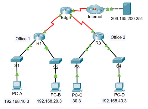
In this lab, you will set up filtering rules for two business locations that are represented by R1 and R3. Management has established some access policies between the LANs located at R1 and R3, which you must implement. The Edge router sitting between R1 and R3 has been provided by the ISP will not have any ACLs placed on it. You would not be allowed any administrative access to the Edge router because you can only control and manage your own equipment.
Topology
Instructions
Part 1: Verify Connectivity
Part 2: Configure and Verify Standard Numbered and Named ACLs
Step 1: Configure a numbered standard ACL.
Step 2: Configure a named standard ACL.
Part 3: Modify a Standard ACL
Step 1: Modify a named standard ACL.
Reflection Questions
R1 Configurations
- R1(config)# interface GigabitEthernet0/0/0
- R1(config-if)# description Connected to LAN 10
- R1(config-if)# ip address 192.168.10.1 255.255.255.0
- R1(config-if)# duplex auto
- R1(config-if)# speed auto
- R1(config-if)# no shutdown
- R1(config-if)# exit
- !
- R1(config)# interface GigabitEthernet0/0/1
- R1(config-if)# description Connected to LAN 20
- R1(config-if)# ip address 192.168.20.1 255.255.255.0
- R1(config-if)# duplex auto
- R1(config-if)# speed auto
- R1(config-if)# no shutdown
- R1(config-if)# exit
- !
- R1(config-if)# interface Serial0/1/0
- R1(config-if)# description Connected to link Edge
- R1(config-if)# ip address 10.1.1.1 255.255.255.252
- R1(config-if)# clock rate 2000000
- R1(config-if)# no shutdown
- R1(config-if)# exit
- !
- R1(config-if)# interface Serial0/1/1
- R1(config-if)# no ip address
- R1(config-if)# clock rate 2000000
- R1(config-if)# shutdown
- R1(config-if)# exit
- !
- R1(config)# interface Vlan1
- R1(config-if)# no ip address
- R1(config-if)# shutdown
- R1(config-if)# exit
- !
- R1(config)# router ospf 10
- R1(config-router)# router-id 1.1.1.1
- R1(config-router)# log-adjacency-changes
- R1(config-router)# network 10.1.1.0 0.0.0.3 area 0
- R1(config-router)# network 192.168.10.0 0.0.0.255 area 0
- R1(config-router)# network 192.168.20.0 0.0.0.255 area 0
- R1(config-router)# end
- R1#
R2 Configurations
- R2(config)# interface GigabitEthernet0/0/0
- R2(config-if)# description Connected to LAN 30
- R2(config-if)# ip address 192.168.30.1 255.255.255.0
- R2(config-if)# duplex auto
- R2(config-if)# speed auto
- R2(config-if)# no shutdown
- R2(config-if)# exit
- !
- R2(config)# interface GigabitEthernet0/0/1
- R2(config-if)# description Connected to LAN 40
- R2(config-if)# ip address 192.168.40.1 255.255.255.0
- R2(config-if)# duplex auto
- R2(config-if)# speed auto
- R2(config-if)# no shutdown
- R2(config-if)# exit
- !
- R2(config-if)# interface Serial0/1/0
- R2(config-if)# no ip address
- R2(config-if)# clock rate 2000000
- R2(config-if)# shutdown
- R2(config-if)# exit
- !
- R2(config-if)# interface Serial0/1/1
- R2(config-if)# description Connected to link Edge
- R2(config-if)# ip address 10.2.2.1 255.255.255.252
- R2(config-if)# no shutdown
- R2(config-if)# exit
- !
- R2(config-if)# interface Vlan1
- R2(config-if)# no ip address
- R2(config-if)# shutdown
- R2(config-if)# exit
- !
- R2(config)# router ospf 10
- R2(config-router)# router-id 3.3.3.3
- R2(config-router)# log-adjacency-changes
- R2(config-router)# network 10.2.2.0 0.0.0.3 area 0
- R2(config-router)# network 192.168.30.0 0.0.0.255 area 0
- R2(config-router)# network 192.168.40.0 0.0.0.255 area 0
Part 1: Verify Connectivity
In Part 1, you verify connectivity between devices.
Note: It is very important to test whether connectivity is working before you configure and apply access lists. You want to be sure that your network is properly functioning before you start to filter traffic.
Questions:
- From PC-A, ping PC-C and PC-D. Were your pings successful?
- From R1, ping PC-C and PC-D. Were your pings successful?
- From PC-C, ping PC-A and PC-B. Were your pings successful?
- From R3, ping PC-A and PC-B. Were your pings successful?
- Can all of the PCs ping the server at 209.165.200.254?
Part 2: Configure and Verify Standard Numbered and Named ACLs
Step 1: Configure a numbered standard ACL.
Standard ACLs filter traffic based on the source IP address only. A typical best practice for standard ACLs is to configure and apply the ACL as close to the destination as possible. For the first access list in this activity, create a standard numbered ACL that allows traffic from all hosts on the 192.168.10.0/24 network and all hosts on the 192.168.20.0/24 network to access all hosts on the 192.168.30.0/24 network. The security policy also states that an explicit deny any access control entry (ACE), also referred to as an ACL statement, should be present at the end of all ACLs.
Questions:
- What wildcard mask would you use to allow all hosts on the 192.168.10.0/24 network to access the 192.168.30.0/24 network?
- Following Cisco’s recommended best practices, on which router would you place this ACL?
- On which interface would you place this ACL? In what direction would you apply it?
a. Configure the ACL on R3. Use 1 for the access list number.
R3(config)# access-list 1 remark Allow R1 LANs Access
R3(config)# access-list 1 permit 192.168.10.0 0.0.0.255
R3(config)# access-list 1 permit 192.168.20.0 0.0.0.255
R3(config)# access-list 1 deny any
b. Apply the ACL to the appropriate interface in the proper direction.
R3(config)# interface g0/0/0
R3(config-if)# ip access-group 1 out
c. Verify a numbered ACL.
The use of various show commands can help you to verify both the syntax and placement of your ACLs in your router.
Questions:
- To see access list 1 in its entirety with all ACEs, which command would you use?
- What command would you use to see where the access list was applied and in what direction?
1) On R3, issue the show access-lists 1 command.
R3# show access-list 1
Standard IP access list 1
permit 192.168.10.0, wildcard bits 0.0.0.255
permit 192.168.20.0, wildcard bits 0.0.0.255
deny any
2) On R3, issue the show ip interface g0/0/0 command.
R3# show ip interface g0/0/0
GigabitEthernet0/0/0 is up, line protocol is up (connected)
Internet address is 192.168.30.1/24
Broadcast address is 255.255.255.255
Address determined by setup command
MTU is 1500 bytes
Helper address is not set
Directed broadcast forwarding is disabled
Outgoing access list is 1
Inbound access list is not set
3) Test the ACL to see if it allows traffic from the 192.168.10.0/24 network to access the 192.168.30.0/24 network.
From the PC-A command prompt, ping the PC-C IP address. Were the pings successful?
4) Test the ACL to see if it allows traffic from the 192.168.20.0/24 network access to the 192.168.30.0/24 network.
From the PC-B command prompt, ping the PC-C IP address. Were the pings successful?
5) Should pings from PC-D to PC-C be successful? Ping from PC-D to PC-C to verify your answer.
d. From the R1 prompt, ping PC-C’s IP address again.
R1# ping 192.168.30.3
Question:
Was the ping successful? Explain.
e. Issue the show access-lists 1 command again. Note that the command output displays information for the number of times each ACE was matched by traffic that reached interface Gigabit Ethernet 0/0/0.
R3# show access-lists 1
Standard IP access list 1
permit 192.168.10.0 0.0.0.255 (4 match(es))
permit 192.168.20.0 0.0.0.255 (4 match(es))
deny any (4 match(es))
Step 2: Configure a named standard ACL.
Create a named standard ACL that conforms to the following policy: allow traffic from all hosts on the 192.168.40.0/24 network access to all hosts on the 192.168.10.0/24 network. Also, only allow host PC-C access to the 192.168.10.0/24 network. The name of this access list should be called BRANCH-OFFICE-POLICY.
Questions:
- Following Cisco’s recommended best practices, on which router would you place this ACL?
- On which interface would you place this ACL? In what direction would you apply it?
a. Create the standard named ACL BRANCH-OFFICE-POLICY on R1.
R1(config)# ip access-list standard BRANCH-OFFICE-POLICY
R1(config-std-nacl)# permit host 192.168.30.3
R1(config-std-nacl)# permit 192.168.40.0 0.0.0.255
R1(config-std-nacl)# end
R1#
*Feb 15 15:56:55.707: %SYS-5-CONFIG_I: Configured from console by console
Question:
Look at the first ACE in the access list. What is another way to write this?
b. Apply the ACL to the appropriate interface in the proper direction.
R1# config t
R1(config)# interface g0/0/0
R1(config-if)# ip access-group BRANCH-OFFICE-POLICY out
c. Verify a named ACL.
1) On R1, issue the show access-lists command.
R1# show access-lists
Standard IP access list BRANCH-OFFICE-POLICY
10 permit host 192.168.30.3
20 permit 192.168.40.0 0.0.0.255
Question:
Is there any difference between this ACL on R1 and the ACL on R3? If so, what is it?
2) On R1, issue the show ip interface g0/0/0 command to verify that the ACL is configured on the interface.
R1# show ip interface g0/0/0
GigabitEthernet0/0/0 is up, line protocol is up (connected)
Internet address is 192.168.10.1/24
Broadcast address is 255.255.255.255
Address determined by setup command
MTU is 1500 bytes
Helper address is not set
Directed broadcast forwarding is disabled
Outgoing access list is BRANCH-OFFICE-POLICY
Inbound access list is not set
Test the ACL. From the command prompt on PC-C, ping the IP address of PC-A. Were the pings successful?
3) Test the ACL to ensure that only the PC-C host is allowed access to the 192.168.10.0/24 network. You must do an extended ping and use the G0/0/0 address on R3 as your source. Ping PC-A’s IP address.
R3# ping
Protocol [ip]:
Target IP address: 192.168.10.3
Repeat count [5]:
Datagram size [100]:
Timeout in seconds [2]:
Extended commands [n]: y
Source address or interface: 192.168.30.1
Type of service [0]:
Set DF bit in IP header? [no]:
Validate reply data? [no]:
Data pattern [0xABCD]:
Loose, Strict, Record, Timestamp, Verbose[none]:
Sweep range of sizes [n]:
Type escape sequence to abort.
Sending 5, 100-byte ICMP Echos to 192.168.10.3, timeout is 2 seconds:
Packet sent with a source address of 192.168.30.1
U.U.U
Question:
Were the pings successful?
4) Test the ACL to see if it allows traffic from the 192.168.40.0/24 network access to the 192.168.10.0/24 network. From the PC-D command prompt, ping the PC-A IP address.
Question:
Were the pings successful?
Part 3: Modify a Standard ACL
It is common in business for security policies to change. For this reason, ACLs may need to be modified. In Part 3, you will change one of the ACLs you configured previously to match a new management policy that is being put in place.
Attempt to ping the server at 209.165.200.254 from PC-A. Notice that the ping is not successful. The ACL on R1 is blocking internet traffic from returning to PC-A. This is because the source address in the packets that are returned is not in the range of permitted addresses.
Management has decided that traffic that is returning from the 209.165.200.224/27 network should be allowed full access to the 192.168.10.0/24 network. Management also wants ACLs on all routers to follow consistent rules. A deny any ACE should be placed at the end of all ACLs. You must modify the BRANCH-OFFICE-POLICY ACL.
You will add two additional lines to this ACL. There are two ways you could do this:
OPTION 1: Issue a no ip access-list standard BRANCH-OFFICE-POLICY command in global configuration mode. This would remove the ACL from the router. Depending upon the router IOS, one of the following scenarios would occur: all filtering of packets would be cancelled, and all packets would be allowed through the router; or, because you did not remove the ip access-group command from the G0/1 interface, filtering is still in place. Regardless, when the ACL is gone, you could retype the whole ACL, or cut and paste it in from a text editor.
OPTION 2: You can modify ACLs in place by adding or deleting specific lines within the ACL itself. This can come in handy, especially with ACLs that are long. The retyping of the whole ACL or cutting and pasting can easily lead to errors. Modifying specific lines within the ACL is easily accomplished.
For this activity, use Option 2.
Step 1: Modify a named standard ACL.
a. From R1, issue the show access-lists command.
Open configuration window
R1# show access-lists
Standard IP access list BRANCH-OFFICE-POLICY
10 permit 192.168.30.3 (8 matches)
20 permit 192.168.40.0 0.0.0.255 (5 matches)
b. Add two additional lines at the end of the ACL. From global config mode, modify the ACL, BRANCH-OFFICE-POLICY.
R1#(config)# ip access-list standard BRANCH-OFFICE-POLICY
R1(config-std-nacl)# 30 permit 209.165.200.224 0.0.0.31
R1(config-std-nacl)# 40 deny any
R1(config-std-nacl)# end
c. Verify the ACL.
1) On R1, issue the show access-lists command.
R1# show access-lists
Standard IP access list BRANCH-OFFICE-POLICY
10 permit 192.168.30.3 (8 matches)
20 permit 192.168.40.0, wildcard bits 0.0.0.255 (5 matches)
30 permit 209.165.200.224, wildcard bits 0.0.0.31
40 deny any
Question:
Do you have to apply the BRANCH-OFFICE-POLICY to the G0/1 interface on R1?
2) Test the ACL to see if it allows traffic from the 209.165.200.224/27 network access to return to the 192.168.10.0/24 network. From PC-A, ping the server at 209.165.200.254.
Question:
- Were the pings successful?
- Close configuration window
Reflection Questions
1. As you can see, standard ACLs are very powerful and work quite well. Why would you ever have the need for using extended ACLs?
2. More typing is typically required when using a named ACL as opposed to a numbered ACL. Why would you choose named ACLs over numbered?